Installation
Setup Guide
ADS-B Antenna and receiver setup instructions
Step 1: Unpacking the Package:
When you receive your package, the following items will be included inside:
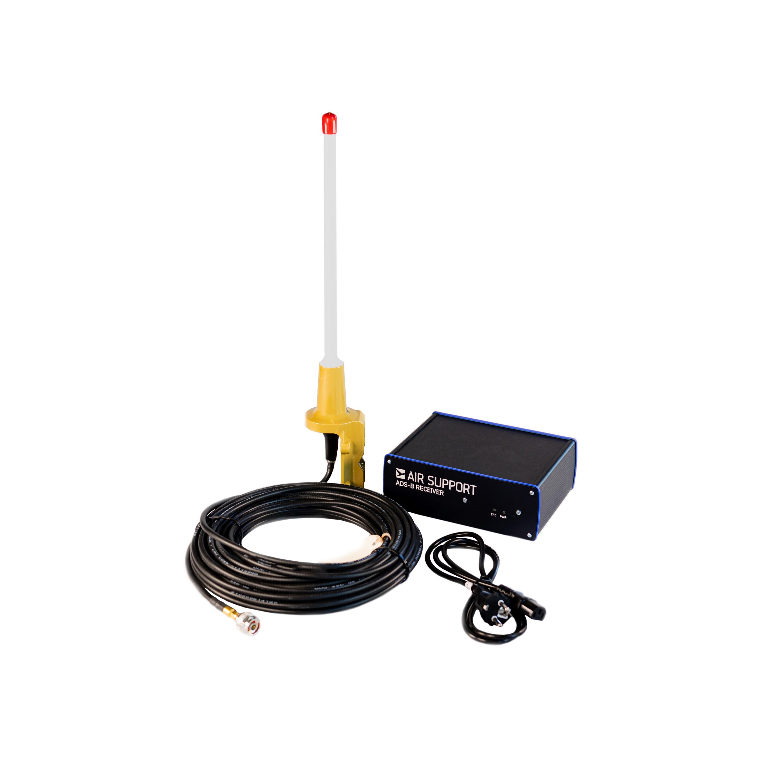
- An ADS-B receiver unit: This is a 21×15,5x8cm black rectangular box with “AIR SUPPORT ADS-B Receiver” on the front.
- An ADS-B antenna: This is a 50cm antenna with a gold base, white body, and red tip. It will be attached to a coaxial cable.
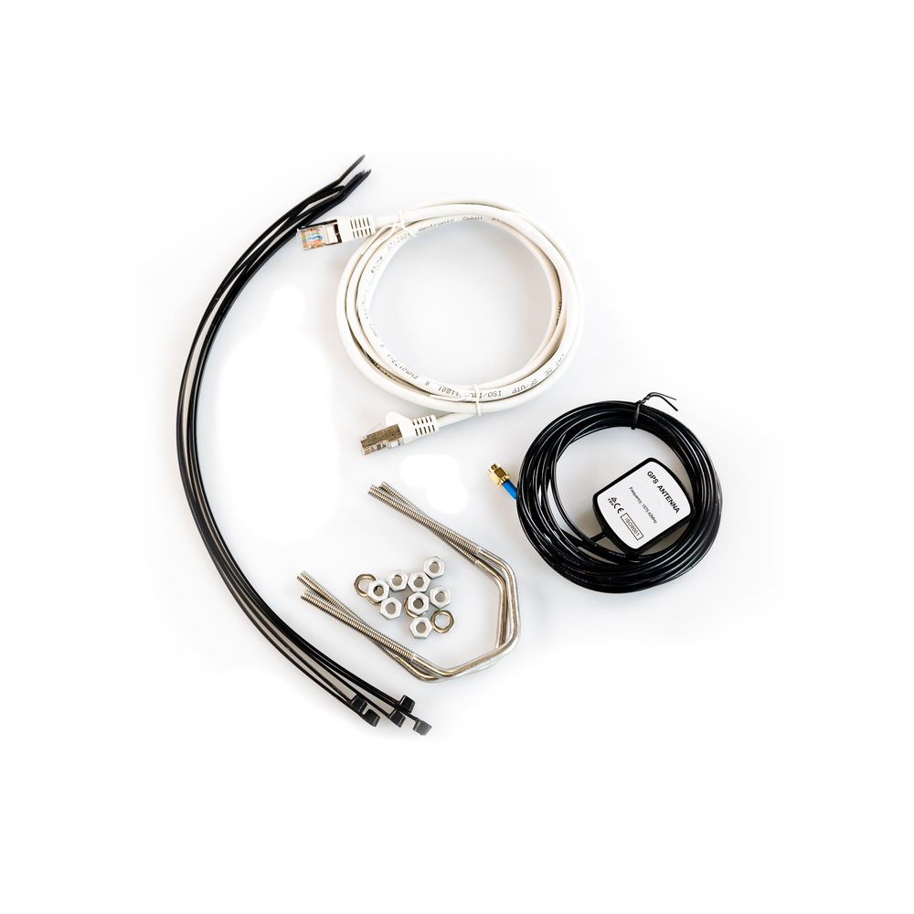
- ADS-B Setup Package: This bag contains, a magnetic GPS receiver, zip ties, an ethernet cable, one receiver power cable, and two antennae mounting brackets.
ADSB receiver kit:

ADSB setup package:

IP Addresses and Ports
The following IP addresses and ports need to be whitelisted on your firewall for the ADS-B receiver to start pushing aircraft data into our server.
IP: 62.243.143.93 Port Channel: 6902 UDP
IP: 62.243.143.98 Port Channel: 80 UDP
IP: 62.243.143.98 Port Channel: 80
Step 2: Selecting your installation location:
- It’s important to be aware that the mounted antenna and receiver box need to be physically connected to one another. Before beginning the installation, it’s a good idea to think through the ideal location so the cable run is not too far from the receiver. We recommend installing the ADS-B antenna on the highest points possible and with a clear 360-degree view. Note: often antenna is mounted underneath and on the same pole as existing antennas. Our ADS-B antenna only receives data; therefore, it will not interfere with any other receivers or antennae on your roof.
- It is always best to go through an existing conduit if there is adequate room. Otherwise, you might have to drill a small hole through the roof or side of the building.
- Make sure to unscrew the 3/4” female adapter from the coaxial cable before feeding it down to the receiver box. *So, you do not lose this adapter, it is best to attach it to the “ADS-B Antenna” screw on the back of the ADSB Support receiver box.
- Ideally, you can mount the antenna within 20 meters of where you place the ADS-B receiver. If you require a longer cable, then we can ship you a separate antenna with a slightly thicker coaxial cable up to 40 meters.
- In the “ADS-B Setup Package” bag there will be two U-Brackets, nuts, bolts, and washers. This is how you attach the antenna to wherever you choose to place it. See the photo below on the U-Brackets should attach to the antenna. Ensure that the co-axial wire is facing away from the pole you attach it to so the wire doesn’t get crimped.
Step 3: Setting up the Receiver:
- Your IT/server room is an ideal location to place the receiver, as there are ample ethernet ports. However, in some situations, the IT/server room might be too far from where an antenna can be practically mounted. In these instances, an installer might choose to place the ADS-B receiver outside of the IT/server room. For example, any office with a live ethernet jack and power outlet will do.
- Once you have selected a location for your receiver, plug one end of the ethernet LAN cable into the port marked “LAN” at the back of the receiver. Plug the other end of the cable into an available ethernet port that has access to the internet.
Once again, your IT department will have to enable access to the following IP addresses and ports:
IP: 62.243.143.93 Port Channel: 6902 UDP
IP: 62.243.143.98 Port Channel: 80 UDP
IP: 62.243.143.98 Port Channel: 80
Email us here: adsb@adsbsupport.com
3. Next, in the same bag, you will see a small square device with an attached cable labeled “GPS Antenna.” Attach this device to the gold screw at the back of the receiver labeled “GPS Antenna”. The GPS antenna is magnetic so that it can be easily mounted to any metal surface. Note: The GPS antenna needs a view of the sky to function correctly. If this is not possible from the receiver’s location, a GPS bracket and extension cable for mounting the GPS antenna with the ADS-B antenna can be supplied.
4. Next, verify that the 3/4” adapter is attached to the large screw connection on the receiver labeled “ADS-B Antenna”. Then attach the smaller 5/16” gold connection from the antenna to the 3/4” adapter.
5. Lastly, plug in and connect the power cable to the receiver. The light above the label that says “PWR” should display a solid green color and the TFC (traffic) light should start flickering. That’s it, you’re done. Your connections should look like the ones displayed in the photo below.
Help and support
Don’t hesitate to contact us if you have any questions do not hesitate to contact us.
Tel: +45 76 500 300
or email us at adsb@adsbsupport.com